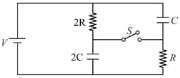
RC, LR and LC Circuits with D.C. and A.C. Sources
RC, LR and LC Circuits with D.C. and A.C. Sources: Overview
This topic covers concepts, such as, Resonance Frequency, Phasor Diagram for Series L-C-R Circuit at Resonance, Discharging Current in R-C Circuit & Electric Circuit etc.
Important Questions on RC, LR and LC Circuits with D.C. and A.C. Sources
A capacitor is connected to source. The capacitive reactance and the RMS current would be:
A series LCR circuit is made by taking . This series combination is connected across an a.c. source of . Calculate (i) the impedance of the circuit and
(ii) the peak value of the current flowing in the circuit.
(iii) Calculate the power factor of this circuit.
An a.c. voltage, , is applied across a
(i) Series RC circuit in which the capacitative impedance is ‘a’ times the resistance in the circuit.
(ii) Series RL circuit in which the inductive impedance is ‘b’ times the resistance in the circuit.
Calculate the value of the power factor of the circuit in each case.
An a.c. source, of voltage , is applied across a series LCR circuit. Which of the following is the phasor diagram for the circuit when capacitative impedance exceeds the inductive impedance?
The instantaneous current and voltage of an AC circuit are given by and . The power dissipation in the circuit is
A resistor of and a capacitor of 15.0 are connected in series to a 220 V, 50 Hz a.c. source. Calculate
(i) The current in the circuit.
(ii) The rms voltage across the resistor and the capacitor.
The instantaneous current and voltage of an a.c. circuit are given by and . What is the power dissipation in the circuit?
An a.c. voltage of , is connected across resistor and inductor in series. What is the impedance of the circuit?
When an inductor and a resistor in series are connected across a , supply a current of flows in the circuit. The current differs in phase from applied voltage by radian. The value of is
What is the power dissipated in an a.c. circuit in which voltage and current are given by
In a series LCR circuit, the voltage across an inductor, capacitor and resistor are , and respectively. What is the phase difference between the applied voltage and the current in the circuit?
Graph showing variation of current with frequency of source in a series circuit is,
An series circuit has and . It is connected across an emf of . The maximum rate which energy is stored in the magnetic field is:
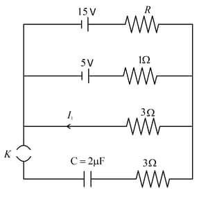
In a circuit shown in the figure, the capacitor is initially uncharged and the key is open. In this condition, a current of flows through the resistor. The key is closed at time . Which of the following statement(s) is(are) correct?
[Given : ]
Consider an circuit, with inductance and capacitance , kept on a plane. The area of the circuit is . It is placed in a constant magnetic field of strength which is perpendicular to the plane of the circuit. At time , the magnetic field strength starts increasing linearly as with . The maximum magnitude of the current in the circuit is____.
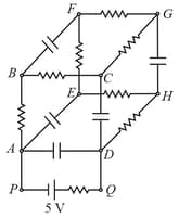
In the given circuit each of the resistors is of resistance and each of the capacitors has capacitance. What is the charge in the capacitor between the points and ?
A resistance is connected in series with a choke coil. When a supply is applied to this combination, the voltage across the resistance and the choke coil are and respectively. Find the power consumed by the choke coil. Also, calculate the power factor of the choke coil and the power factor of the circuit.
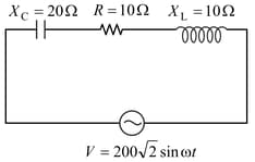
In the LCR circuit shown in figure
In the circuit shown in the figure, the key is closed at time .
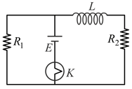
Initially switch was closed for long time. Switch is opened at . Take , . At time
